
· OWON Technology · Smart Energy Meters · 9 min read
Sizing a PC471 Open-Type CT: Bores, Ratings and Non-Standard Orders
Six bores from Ø10 to Ø51 mm, 20–300 A single-phase and 80–750 A three-phase: how to size a PC471 open-type CT, and which sizes are built to order.
An open-type CT is sized by two numbers — the bore that has to close around the cable or busbar, and the current rating that matches the real maximum current — and it is constrained by three ordering rules that only surface at quote stage.
Every PC471 meter measures through open-type (split-core) CT clamps, so the CT is the part of the system that has to fit the installation physically before anything else can be settled. The clamp closes around a conductor that is already in service: no cable is cut and no supply is interrupted. What has to be right is the fit and the rating.
This post covers CT sizing only. If the meter model itself is still open, the PC471 series selection guide puts CT fit where it belongs — step 2 of four steps to a model number, after the electrical system type and before the decision about where the data goes.
Two lines sit behind the range. The single-phase PC4711 line takes up to 2 CTs, rated 20–300 A, with bores of Ø10 / 16 / 20 / 24 mm. The three-phase PC4713 line takes up to 3 CTs, rated 80–750 A, with six bores up to Ø51 mm. Which line a site is on is a model question; which clamp inside that line is a CT question, and that is what follows.
What is the cable or busbar diameter?
CTs are sold by inner diameter, and the clamp has to physically close around the conductor:
Ø10 · Ø16 · Ø20 · Ø24 · Ø36 · Ø51 mm
Measure the overall outer diameter of the insulated cable (or the busbar). If it is larger than Ø24 mm, only the three-phase six-option CT range fits — which rules out the single-phase models for that circuit.
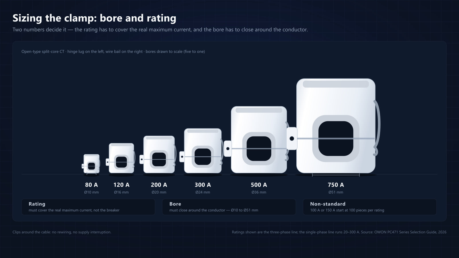
That is a physical constraint before it is a commercial one. The figure to take is the outside diameter of the conductor as it stands, insulation included, because the clamp closes around the cable as installed. The six diameters are not a menu that sits beside a separate menu of ratings either: rating and inner diameter map one-to-one, so the bigger the current range, the bigger the clamp. In the product data the pairing runs:
| CT rating | Inner diameter (bore) |
|---|---|
| 80 A | Ø10 mm |
| 120 A | Ø16 mm |
| 200 A | Ø20 mm |
| 300 A | Ø24 mm |
| 500 A | Ø36 mm |
| 750 A | Ø51 mm |
The single-phase line uses the first four of those bores; the three-phase line uses all six. The 120 A / Ø16 mm clamp is the default that ships with a single-phase meter. Because rating and bore move together, a circuit that needs a rating above 300 A also needs a bore above Ø24 mm — a combination that does not exist on the single-phase line at all.
How much current flows?
Current ratings available across the family: 20 to 300 A on the single-phase line, 80 to 750 A on the three-phase line.
| Model group | Max CTs | Current options | Inner diameters |
|---|---|---|---|
Single-phase (PC4711) | 2 | 20 / 50 / 80 / 120 / 200 / 300 A — the 120 A clamp is the default, and 20 A and 50 A are built to order | Ø10 / 16 / 20 / 24 mm |
Three-phase (PC4713) | 3 | 80 / 120 / 200 / 300 / 500 / 750 A — 100 A and 150 A from 100 pcs per rating | Ø10 / 16 / 20 / 24 / 36 / 51 mm |
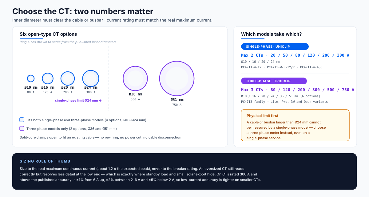 CT rating and inner diameter map one-to-one: the bigger the current range, the bigger the clamp. Rings are drawn to scale.
Size for the actual maximum current, not the breaker rating — an oversized CT loses resolution at the low end, which matters when you are trying to see a standby load or a small solar export.
Three ordering details sit behind that table, and all three are cheaper to settle before a quote than after one:
- 20 A and 50 A are built to order on the single-phase line — supported, but not stocked.
- 100 A and 150 A are not standard ratings on the three-phase line. The nearest stocked options are 120 A or 200 A, and a non-standard rating is a production run: from 100 pieces per rating.
- The 120 A / Ø16 mm clamp is the default that ships with a single-phase meter, so a site that states no preference receives that one.
Sizing down is usually the better mistake to make. Because the bore follows the rating, a clamp bought for headroom the site never uses also arrives with a larger jaw and a low-current band that starts higher — the band table further down shows where the ±1% window begins for each rating.
Two CTs, not three, on a 3P3W service
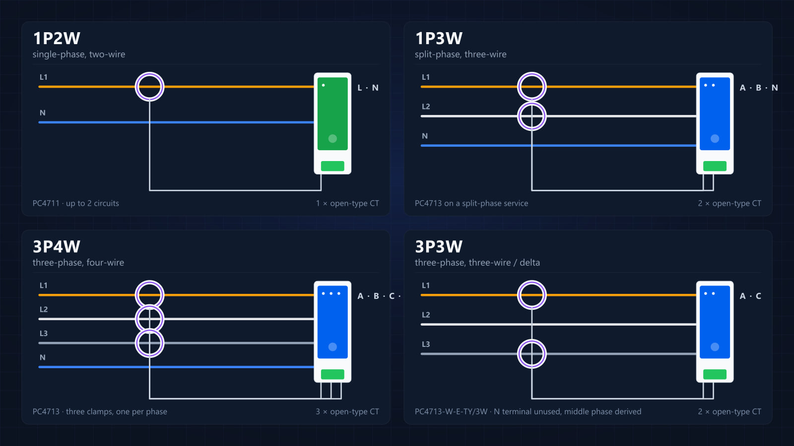
One CT count in the family does not follow the table. On a three-phase three-wire (3P3W) service the installation uses two CTs, not three, because the middle phase current is derived rather than measured. A 3P3W project should therefore be quoted with two CTs in the 80–750 A range.
Two footnotes belong with that number. The family specification still lists “max 3 CTs” for the 3P3W model, so confirm the CT count and the part numbers with OWON when the build is quoted. And the wiring itself — why a 3P3W service needs a different input stage, and how the conductors land on the meter — is covered in the wiring and commissioning guide.
A note on CT options in the source guide
One inconsistency in the older printed material is worth knowing before a quote is built from it: two older documents print the three-phase CT range on a single-phase row. The confirmed split is 20–300 A on the single-phase line and 80–750 A on the three-phase line, and the single-phase line starts at a 20 A clamp. The selection guide carries the full erratum next to the specification matrix.
The habit that avoids the problem is the one this post has followed throughout: quote the clamp by rating and by model line, not by the family row. A CT specification is complete when it names the rating, the inner diameter and the meter model it will be connected to.
”How do I know which CT rating to order?”
Size to the real maximum current, not the breaker. Single-phase ratings run 20 to 300 A and three-phase ratings 80 to 750 A, with inner diameters of Ø10 / 16 / 20 / 24 / 36 / 51 mm. The default clamp is not the same on the two lines: single-phase meters ship with the 120 A / Ø16 mm clamp as standard, while three-phase builds are quoted around the 80 A / Ø10 mm clamp — so state the clamp you need on the order line, because the model number does not fix it. The inner diameter must clear the conductor — anything above Ø24 mm rules out a single-phase model. Two constraints are better stated up front than discovered at quote stage: 100 A and 150 A are not standard ratings — the nearest stocked options are 120 A or 200 A, and a non-standard rating is a production run of 100 pieces per rating — and on the single-phase line the 20 A and 50 A clamps are supported but not stocked. The main CT is open-type and clips on, so no cable is cut and no supply is interrupted.
How to read the accuracy bands
Class B (1%) is the headline accuracy figure, but it is not the number to size a CT against. Current accuracy is published as a band per CT rating, and the band is what decides whether the clamp you picked can see the load you actually care about.
Voltage is ±1%. For current, the base statement is ±1% at rated current and ±2% at low current — and the published bands spell out where “rated” begins and what “low” costs:
| CT rating | ±1% band | ±2% band | ±5% band |
|---|---|---|---|
| 80 A (Ø10 mm) | 1–80 A | below 1 A | — |
| 120 A (Ø16 mm) | 2–120 A | below 2 A | — |
| 200 A (Ø20 mm) | 2–200 A | below 2 A | — |
| 300 A (Ø24 mm) | 6–300 A | 2–6 A | below 2 A |
| 500 A (Ø36 mm) | 6–500 A | 2–6 A | below 2 A |
| 750 A (Ø51 mm) | 6–750 A | 2–6 A | below 2 A |
Read the table from the left. The ±1% band runs all the way up to the clamp’s full rating, so the figure that matters is where it starts: at 1 A on the 80 A clamp, at 2 A on the 120 A and 200 A clamps, and at 6 A on the 300 A, 500 A and 750 A clamps — which are also the three ratings that add a third, ±5% band below 2 A.
That start point is the reason not to over-size. A 750 A clamp does not read a 3 A standby load with the same confidence as an 80 A clamp: at 3 A the big clamp is inside its ±2% band, and below 2 A it is in ±5%, while the 80 A clamp holds ±1% from 1 A up to its full rating. The published bands are also better than the general rule of thumb, which is 1% accuracy above 5% of the CT range — 5% of a 120 A clamp is 6 A, and this one holds ±1% from 2 A.
One question sits underneath the bands rather than inside them: how the meter is calibrated on the loads the site actually has. Solar inverters, LED drivers, switch-mode power supplies and EV chargers are non-linear loads with a capacitive component, and a meter calibrated only on a resistive test bench can drift on exactly those loads — so ask what the calibration covers before a site full of them is signed off. And the family is positioned as a monitoring and control meter at Class B (1%), not a certified revenue meter.
Taken together, the CT decision is smaller than it looks: measure the conductor to fix the bore, then choose the smallest rating whose ±1% band starts low enough to see the load you are trying to measure.
Ready to specify a CT for a PC471? Compare the range on our smart meters page, or talk to our team with the model line, the conductor diameter and the real maximum current, and we will confirm the rating, the bore and the part number.
Frequently Asked Questions
How do I choose the right CT?
Two parameters matter — the inner diameter (must clear the cable or busbar: Ø10, 16, 20, 24, 36 or 51 mm) and the current rating. Ratings run from 20 A to 300 A on the single-phase UniClip models (20 A and 50 A are supported but not stocked) and 80 to 750 A on the three-phase TrioClip models; 100 A and 150 A are non-standard and start at 100 pieces per rating. Single-phase meters take up to 2 CTs and three-phase up to 3 — except on a three-phase three-wire (3P3W) service, where only the PC4713-W-E-TY/3W is specified and the wiring uses 2 CTs because the middle phase current is derived.
Are 100 A or 150 A CTs available, and can a non-standard rating be ordered?
Single-phase ratings run from 20 A to 300 A — the 120 A clamp is the default, and 20 A and 50 A are supported but not stocked. Three-phase ratings run from 80 A to 750 A, with bores of Ø10 / 16 / 20 / 24 / 36 / 51 mm; three-phase builds are quoted around the 80 A / Ø10 mm clamp, so state the clamp you need on the order line. 100 A and 150 A are not standard ratings — the nearest stocked options are 120 A or 200 A — and a non-standard rating is a production run: from 100 pieces per rating. The CT is open-type and clips on, so no cable is cut and no supply is interrupted.
How accurate is the metering?
Class B (1%) as stated in the product release, consistent with the published figures: voltage ±1%, and current ±1% at rated current / ±2% at low current, with the current band specified per CT rating (300 A and above: ±1% from 6 A up, ±2% between 2–6 A, ±5% below 2 A). Operating range is −20 °C to +55 °C at ≤ 90 % RH (non-condensing).
Can a clamp be fitted around a busbar, or only around a cable?
Both. The clamp has to close around the conductor, so what matters is the outer dimension of whatever passes through it — an insulated cable or a busbar. Size by that dimension against the published bores (Ø10 / 16 / 20 / 24 / 36 / 51 mm) and remember the single-phase line stops at Ø24 mm. Above Ø51 mm there is no standard clamp: ask your sales contact about a custom bore before the quote.
Why does capacitive versus resistive load calibration matter?
Because those are the loads a solar or commercial site is full of, and a meter calibrated only on a resistive test bench can drift on them. Solar inverters, LED drivers, switch-mode power supplies and EV chargers all have a capacitive component, so the question to ask any supplier — OWON included — is what the calibration covers.